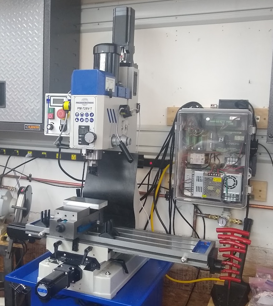
The ballscrew shafts have 10mm ends and the couplers that came with it fit 1/2" and 3/8" stepper shafts only. My motors had 14mm and 10mm shafts and required the purchase of new couplers.
The X/Y motor mounts were made for NEMA-23 spacing and I used NEMA-24 motors (for more power) and I had to 3D print new mounts. This doesn't affect the backlash/accuracy since the ballscrew bearing mounts didn't require changing / modification.
#6-19 x 1/2" thread rolling screws (made for plastic) fit the enclosure mounting plate well
I 3D printed the following: X-axis motor mount for NEMA-24, Y-axis motor mount for NEMA-24, NVCM Mount, power supply mount, and Thermometer Mount - These are available on my Thingiverse account
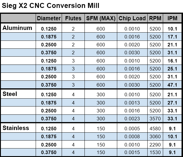
Here is a table of speeds and feed for a Sieg X2 Mini-Mill (Harbor Freight, Grizzly, etc.). These are for the most common bit sizes that I use.
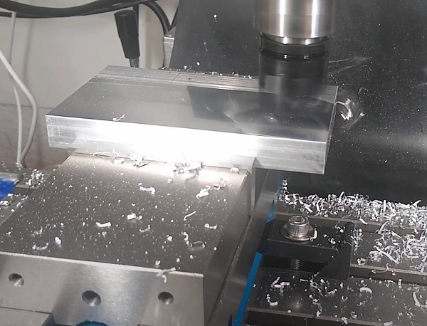
Depth of cut must be less than 50% of the bit diameter. This is adjusted according to the rigidity and power of your machine. For example, with my machine, I can do about 0.055" depth of cut with a 0.250, 3 flute Endmill into aluminum. My machine is bolted to a 1" steel plate and the column has been filled with melted lead to reduce vibrations.
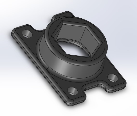
Anti-Backlash / Anti-wobble Mod for Solidoodle 4
In my quest for the perfect 3D printer settings, I decided to try the lift option which lifts the extruder from the surface during
non-extruding moves. I found that my stock Solidoodle 4 had significant backlash in the z-axis. I tried to print out an anti-backlash
nut/spring assembly from Thingiverse but it was made for previous version and my Solidoodle 4 didn't have a long enough z-axis threaded
rod to keep the nut on it when in the highest position.
After thinking about this for a while, I considered just printing a solid piece that holds a nut but thought that it needed some give to
keep it from wearing the rod or becoming sloppy over time. I settled on using a rubber O-ring below the nut to provide springiness. It uses
a 3/8" ID O-ring, 5/16-16 Stainless Steel Nut, and 4-40x3/8 screws w/nuts to hold it to the machine. There are only two screws in the unit since
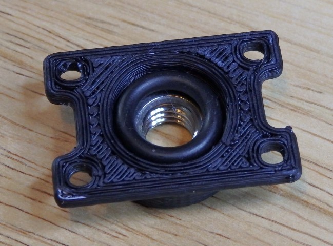
the nut is snug on the O-ring, the mount only has to keep the nut from turning. Here are the components and assembly
Here is a video of the part in operation:
The files are available here as SLDPRT
and STL files.
CNC Vacuum Power Control and Z-axis Auto-zero
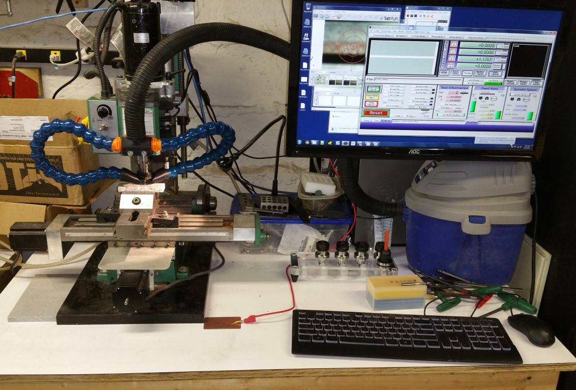
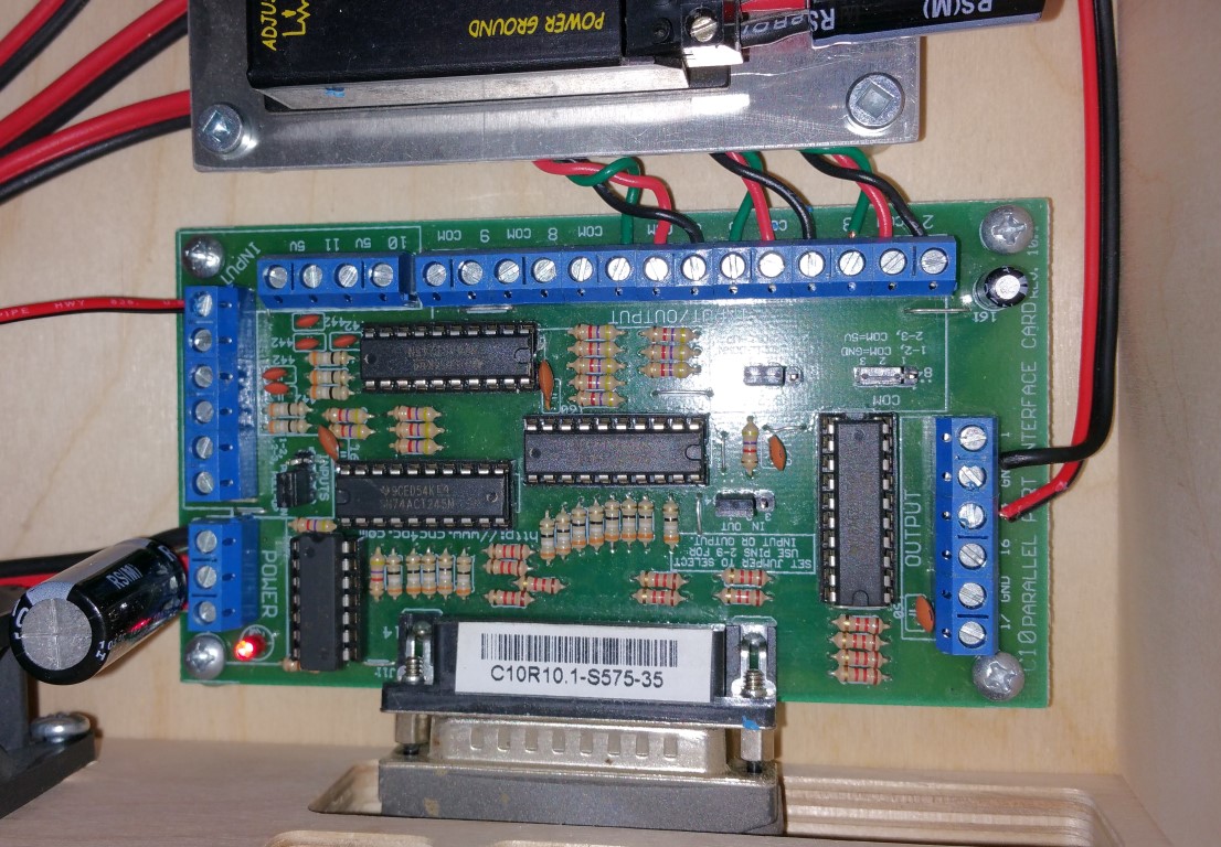
I finally got around to adding Z-axis auto-zeroing to my Mini Mill. With my C10 Parallel Port Breakout board, it was pretty simple.
Just connect a ground wire to the machine from the ground of the board/power supply and connect the probe wire to the Pin 12 (or any other)
input on the breakout board. Make sure the jumper it set to pull-up on the inputs and you're done.
Also, the small vacuum is now controlled by Mach3. It turns on and off with the spindle control which isn't implemented on my system yet
since the Mini-Mill can't be turned on/off with power directly.
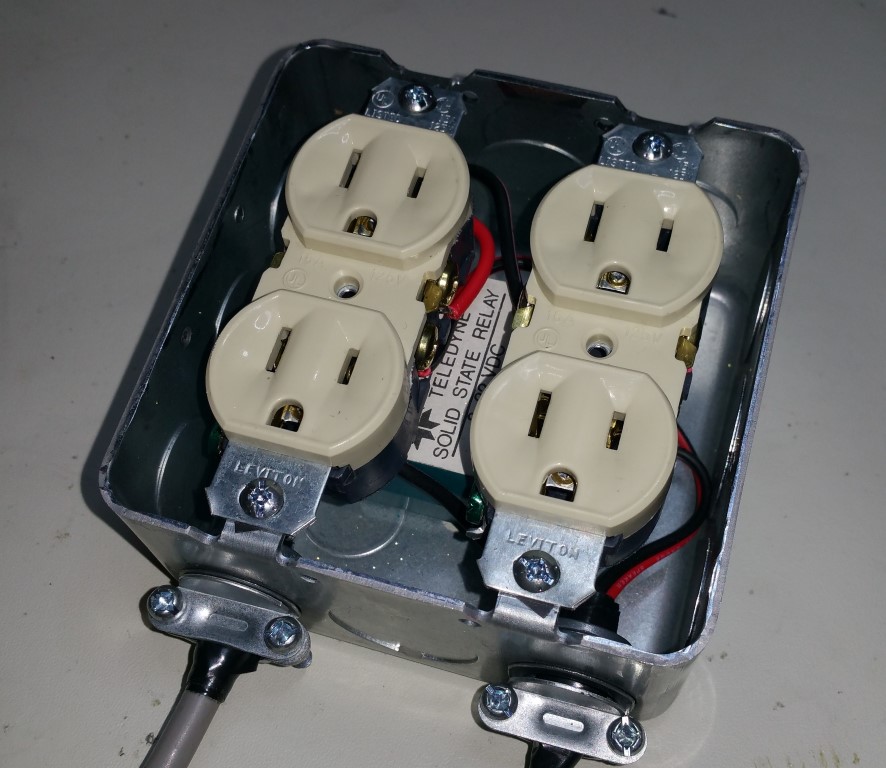
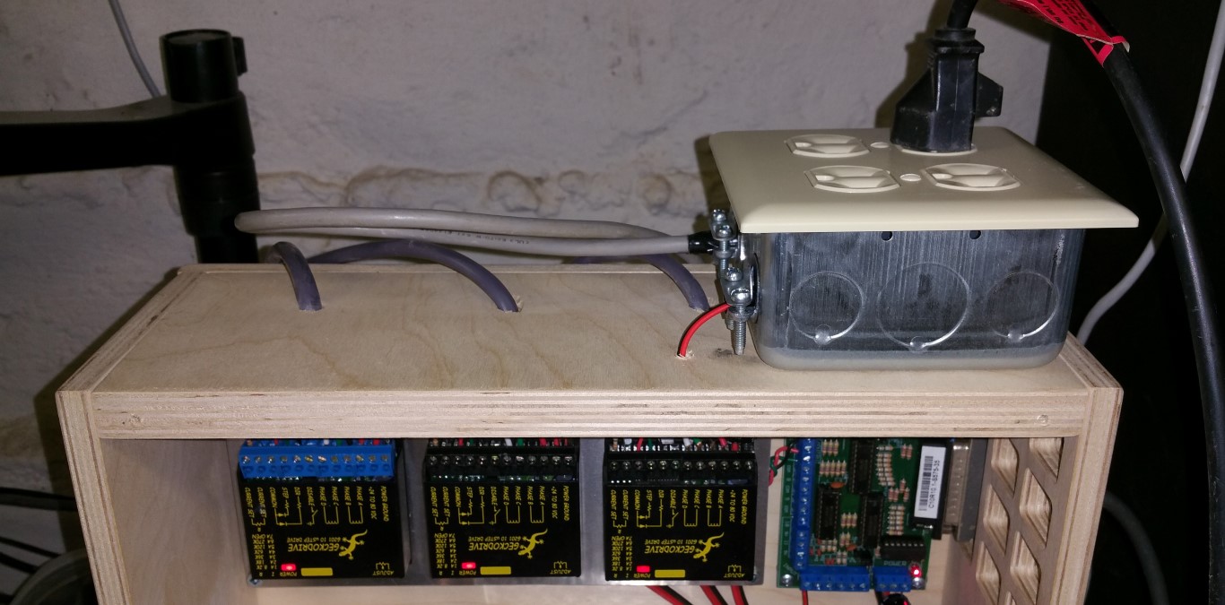
This is also a pretty simple mod. I used a Solid-State Relay (10A with 3-30V control input) and mounted it inside of a power box with two
duplex receptacles. The control is connected to the ground and output pin 14 on my breakout board and Mach3 is set to control this pin. I
need to add a charge-pump into this since the pin is high when the PC boots and turns on the vacuum until Mach3 is loaded. This isn't that
big of a deal if you are only controlling a vacuum but if you use this for a spindle, you should use a charge-pump for safety.
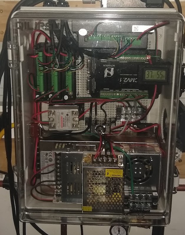
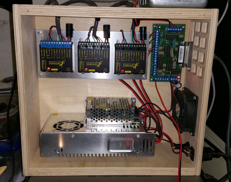
Here is what the inside of my Mini-Mill control box and the breakout board looks like now
3D Printed Magnetic Microscope Camera Mount for CNC Zeroing
It has always been a pain to use the mechanical or laser edge finder in my CNC mill. Although I am usually pretty close, it takes
time and requires me to get up close to the work to look at it from different angles. I have always liked the Microscope Camera systems
on professional CNC machines.
I recently purchased a Supereyes B008 for electronics inspection and have been happy with the performance so
I bought the less expensive Supereyes B005
for about $28 on Amazon to use in my CNC setup. I know that Mach3 has a camera interface and the B005 shows up as a standard camera in
Windows so I thought that it should work. I had some concerns about making the mount adjustable in both X & Y directions so that the unit
can be aligned so height above the work piece won't have significant effect.
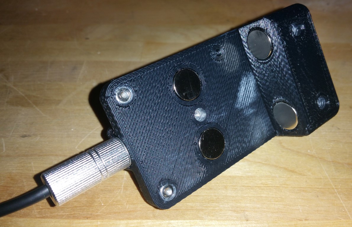
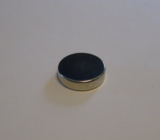
I opted to use strong 1/2" x 1/4" Neodymium magnets from Amazon to
mount the unit. The top section has two on the bottom and the bottom part has two on the top so that the top pulls toward the mill head (left)
and the bottom part pulls up to keep the unit securely attached to the head. The magnets are epoxied into the top and bottom recesses.
1/4-20x3/4" stainless steel set screws are used to hold the Microscope Camera into the holder and to provide adjustment in the X direction.
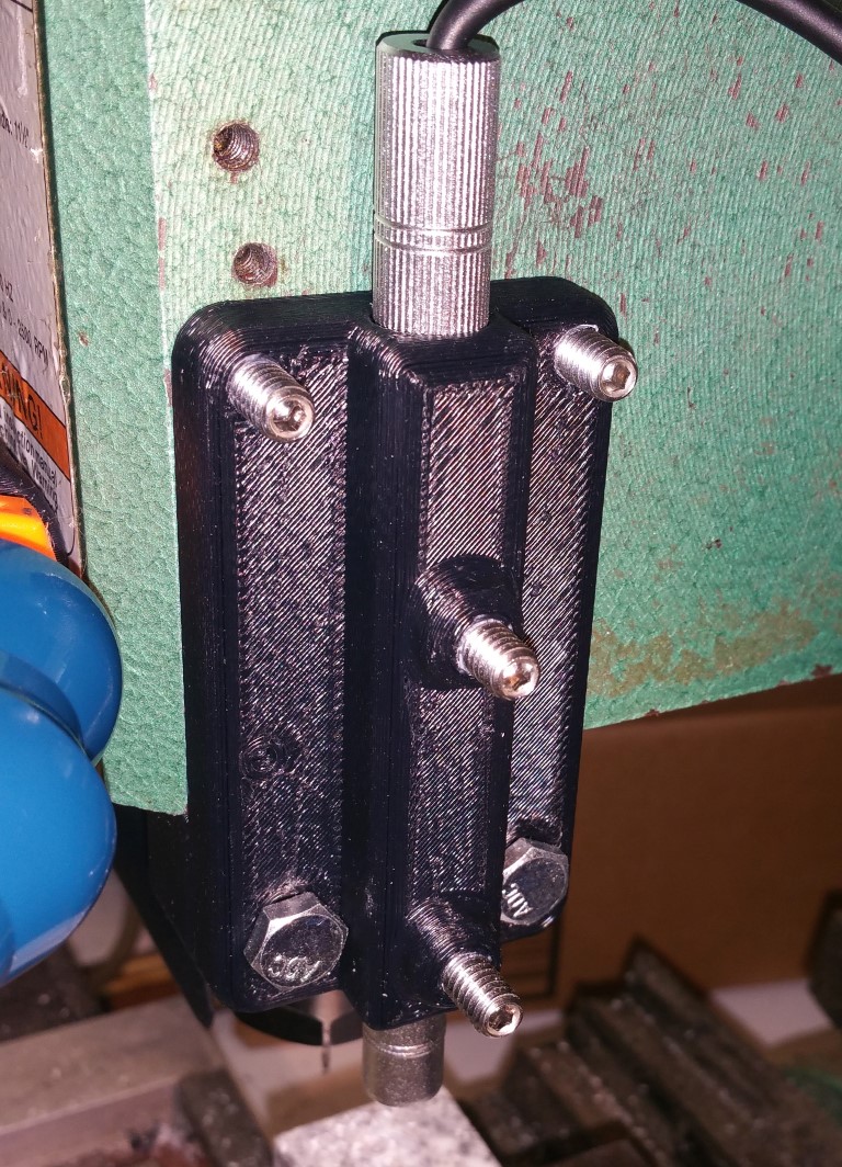
Adjustment in the Y direction is accomplished by loosening the 1/4-20 screws that hold the top to the bottom and tighening when aligned
properly. I've got bolts installed right now but can't tighten them too much but will get some screws and washers on this soon.
This is the assembled unit
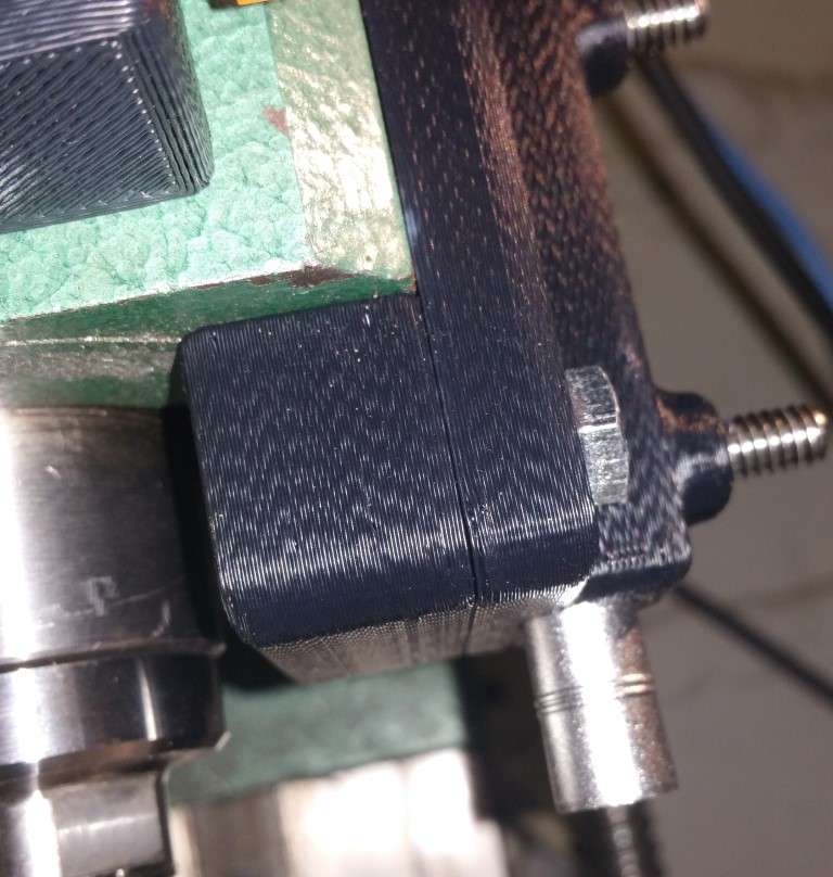
Here on some photos of it attached to my machine
Here is a screenshot of SuperEyes software viewing a nickel
I've got less than $40 in this project and can't wait to get it tested on my machine. Here is some video of it
in operation on my machine
The files for the top are available here as SLDPRT
and STL files.
The files for the bottom are available here as SLDPRT
and STL files.
Custom Vacuum Nozzles for My Loc-Line® Setup
The nozzles that came with the Loc-Line® kit are meant for liquid and aren't shaped well for use as a vacuum so I decided to
make my own with my Solidoodle.
The walls on these are thin enough to be somewhat flexible but are suprisingly strong. It took a few tries to get the fit correct
to mate up to the Loc-Line®
These mate to 3/4" Loc-Line®. The photo in the previous article shows them on the machine.
The files are available here as SLDPRT
and STL files.
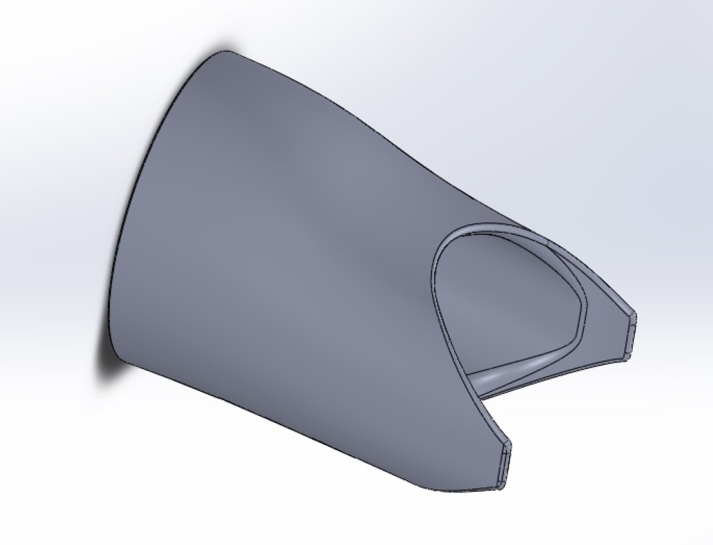
SECOND TRY: Adding a Dual Loc-Line®; Vacuum to a CNC Mini-Mill
I overestimated the flexibility of the Loc-Line®. With the connections pointing down there is no way to make the bend
that I need to get the nozzle close to the bit,
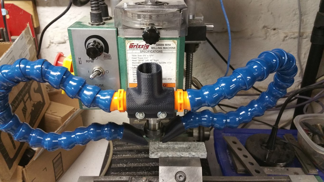
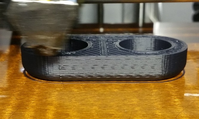
This will bolt onto the front of the Mini-Mill using two existing holes that used to hold on the shield. Here are some photos of
the Vacuum Manifold being 3D Printed
Here is the setup installed on my CNC Mini-Mill
The files are available here as SLDPRT
and STL files.
Adding a Dual Loc-Line®; Vacuum to a CNC Mini-Mill
I've been machine more things on my CNC Mini-Mill and am getting tired of sweeping up or holding a Shop-Vac®;
hose up to the machine
My latest CNC project
So I found that Loc-Line®; is available in 3/4" diameters
which is about right for two of them to be connected to a small Shop-Vac®;. They will need to be rigidly mounted to the head of
machine to maintain the same position relative to the cutter and also split the Shop-Vac®; hose to two 3/4" NPT connections.
There is no adapter that fits the requirements so I decided to make one from ABS on my Solidoodle 3D Printer.
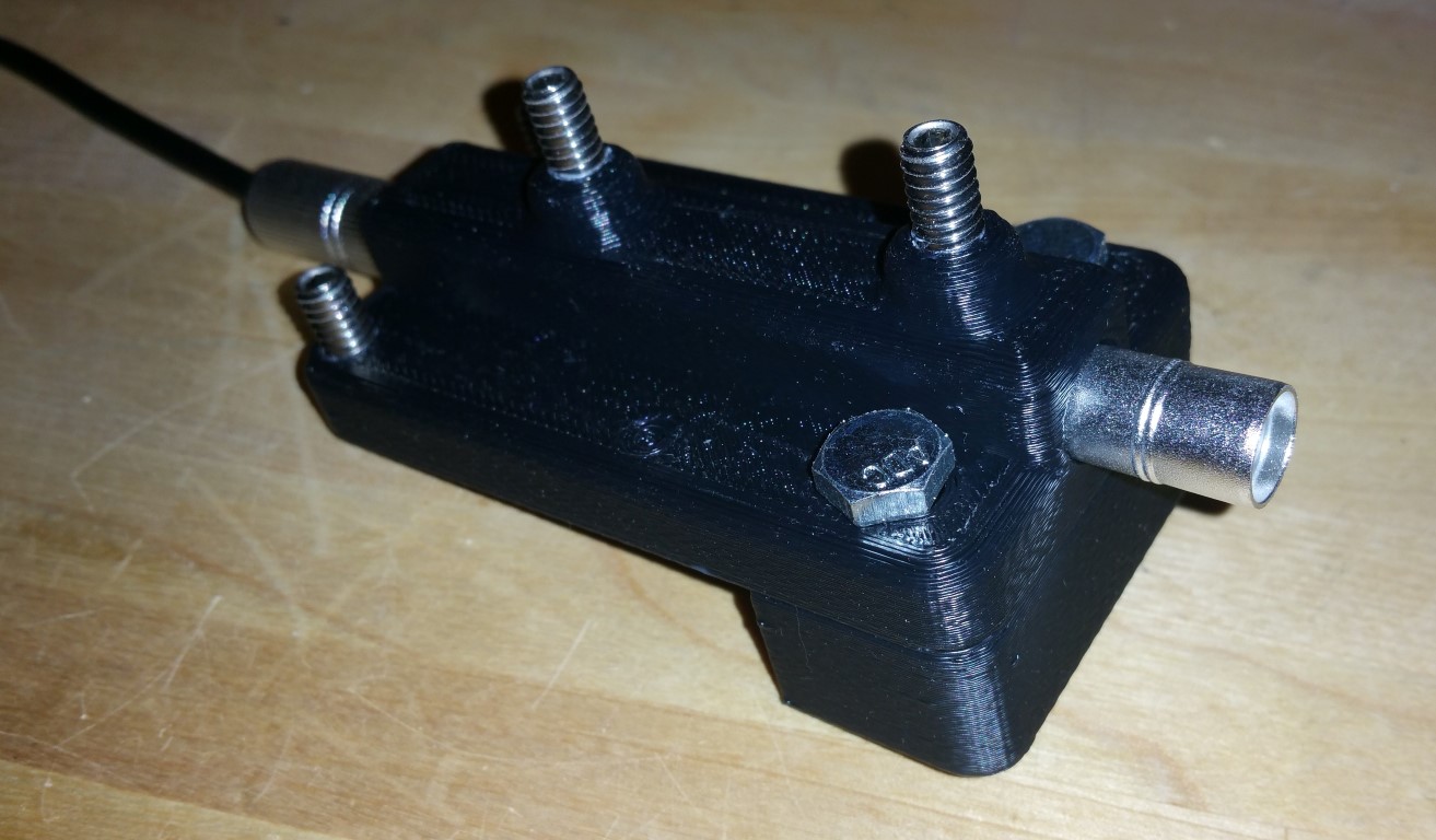
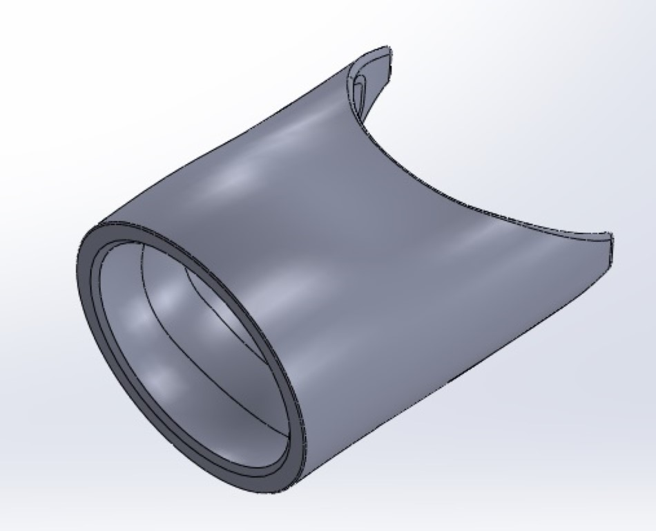
I designed the manifold using Solidworks and the files are available here as SLDPRT
and STL files. It looks like this
This will bolt onto the front of the Mini-Mill using an existing hole and will be tapped with a 3/4" NPT tap to accept the
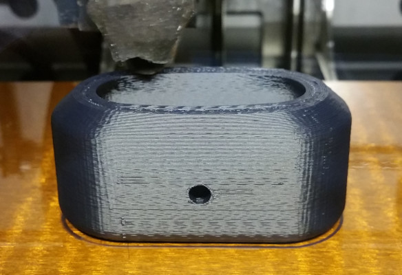
Loc-line®;. The other side is sized at 1.3" to connect to the Shop-Vac®; hose with the end removed. Here are some photos of
the Vacuum Manifold being 3D Printed and the finished product
The effects of missed steps on a CNC router
When a CNC router using stepper motor "misses steps" the physical reference to zero on the workpiece
moves. Here are some examples.
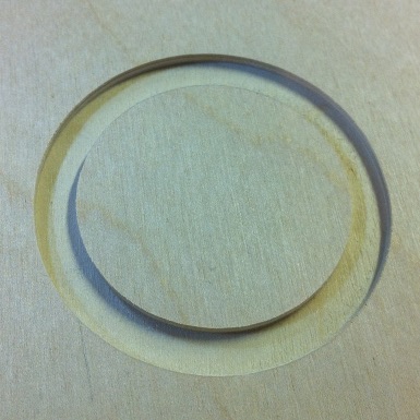
These 2" circles are cut .1" deep by cutting .005" at a time (the bit travels around 20 times to cut this)
The left one has square sides as you would expect. The right one shows that the CNC router is missing
steps -- note the slope on the sides caused by the machine "floating" over a little bit on each pass.
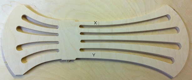
On a real object this can manifest itself by giving really poor results. Here is a chair back that
was done for my neighbor to replace a broken one. Note that the rungs "X" and "Y" are supposed to
be the same width.
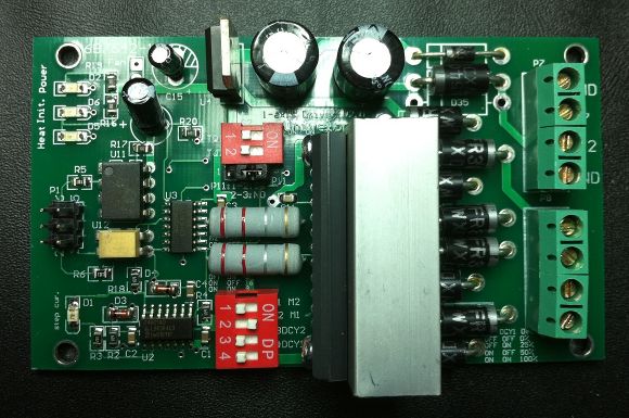
Problem and Fix for the Univelop / CNCgeeker.com TB6560 stepper motor driver missing steps
THE PROBLEM:
I purchased the bipolar stepper drivers for my new CNC machine from CNCgeeker.com because I liked that they have
a modular design (each axis with its separate driver board). I got the electronics put together on the workbench
and connected to motors and everything seemed to be fine but after I got the machine together, I noticed that it
was missing steps in every axis and this was reproducible with exactly the same error and not speed dependent.
After messing with nearly every setting on Mach3 and the computer parallel port, I suspected the driver board.
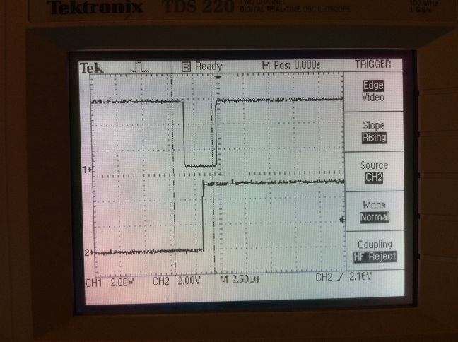
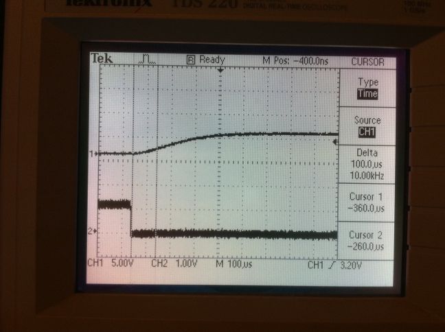
I probed the step and direction pins on the TB6560 with my oscilloscope and found the following:
The top trace is the step pulse and the bottom is the direction. Notice that the direction pulse is changing AFTER
the step pulse changes. This causes the motor to step in the WRONG DIRECTION every time there is a direction change.
This adds up quickly! I looked at the input to the board and saw the following:
Notice that on the input to the driver board, the step pulse is after the direction pulse by 16uS which is what
should be happening. I probed the output of the P521 optocoupler and found the following:
The top trace is the output (collector) of the P521 optocoupler and the bottom trace is the input (LED). Note the
VERY significant rise time. I found that the collector is being pulled high with a 100kohm (SMT0805 / 104) resistor
which is WAY too big for this application. The parallel port breakout has a 330 ohm (SMT0805 /331) resistor on its output
that is in series with a 100 ohm (SMT0805 / 101) resistor which gives 430 ohms total. With a 5V source and
nominal 1.15V across the LED, we have about 9 milliamps which is a bit low for this part (datasheet recommends 16 to 25mA)
but probably ok.
The real issue is that the step and direction lines go through two different types of optocouplers. The step pulse
goes through a high-speed 6N137 (10Mbps rated) optocoupler and the direction pulse goes through a standard type P521
optopcoupler which is 200KHz in the best case (10V supply / high current). The direction signal is delayed by the
rise/fall time of the slow part (5 to 25 microseconds) and the step signal is delayed by the rise/fall time of the fast part
(20 to 100 nanoseconds).
THE FIX:
I replaced the 100k ohm (SMT0805 / 104) resistor(labelled R18) with a 220 ohm (SMT0805 / 221) resistor, shorted across
the 100 ohm (SMT0805 / 101) resistor (labelled R6 ), style="color: rgb(255, 255, 255);">and changed Mach3 to use 10uS
pulses (the motor tuning says 1-5 but you can enter 10 and it will work). The board now provides the direction change
to the TB6560 IC about 5 to 10 uS before the step pulse which isn't optimal (should be the 16+uS output from the parallel
port) but functions correctly without missing steps.
SUMMARY:
The board design seems ok except for this issue but the vendor/design takes quite a while to respond (I emailed him
about this issue but haven't received a response yet). If you aren't comfortable soldering SMT components then
this board isn't for you since in its off-the-shelf state, it WILL MISS STEPS.
How to set up a touch plate for auto-zero of the Z-axis in Mach3
The idea is to use the cutter itself and a soft conductive plate as a switch that triggers the probe
input on Mach3. The touch plate is connected to a parallel port input pin that is pulled up to +5V with a 10k resistor
and the ground is connected to an alligator clip. The ground is clipped onto the cutter bit and the touch plate is held
on the work surface. Clicking the Auto Tool Zero button runs the Visual Basic code that lowers the cutter until it gets
a signal from the probe input, sets the Z-axis readout to the thickness of the touch plate (.060" in my case) then raises
the cutter to 1 inch above the surface.
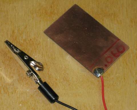
For the touch plate, I used .060" thick PCB material. This is inexpensive and can be gotten from many sources. I
recommend looking on ebay and searching for
copper clad board.
Here is a demonstration of the setup in action.
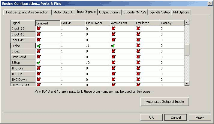
First we set up the input pin for the probe. We need to have it configured to the proper pin with an active low input
since it is normally pulled up to 5VDC.
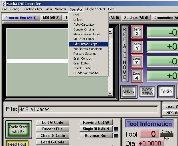
Then we need to add the Visual Basic code to the button. We go to the Operator menu then click on Edit Button Script.
The configurable buttons will now be flashing and we click on the Auto Tool Zero button. This will bring up an editor
that may have a Not Implemented message in it. Copy the code below into this editor replacing any existing code. You
will want to modify the .060 value to match the thickness of your touch plate. Save the file (same name) and exit the
editor then restart Mach3. You should now be able to press the Auto Tool Zero button and have the Z-axis lower until the
touch plate connection is made. I suggest that you try touching the alligator clip and plate together the first few times
with the Z-axis nohwere near the table to make sure that this is working.
VB Code for Auto Tool Zero Button
		Message( "Auto Zeroing..." )
		If IsSuchSignal (22) Then
		code "G31 Z-3 F20"
		While IsMoving()
		Wend
		Call SetDRO( 2, .060 )
		code "G1 Z1"
		End If
"Moving Knot" Cable / Pulley System to Reduce/Eliminate Racking on a Moving Gantry CNC Router
After designing and building my latest CNC Router (23" x 36"), I found that I was still seeing a lot of
racking of the gantry during cutting that shows up as chatter when the router is far from the middle of the
table. I was able to measure about .050" of racking movement by pushing on one side of the gantry. After a lot
of research and not wanting to add a second leadscrew (dual x-axis setup), I found a discussion of the "moving
knot" on a CNCzone
forum. This design has been used for 100's of years on drawers and drafting tables to eliminate the racking action
in their mechanisms.
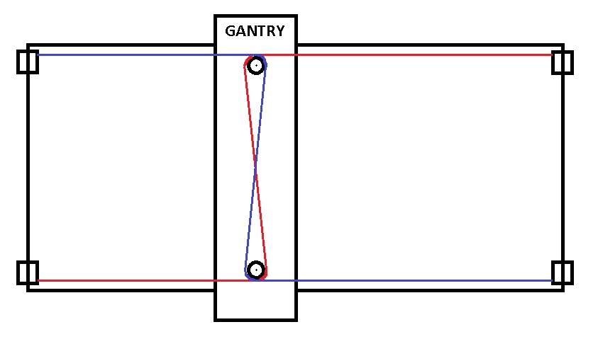
The system works by having two cables that each prevent the gantry from rotating. By having these two forces oppose
each other, rotation of the gantry (the racking movement) is prevented. Here is a diagram of what is going on:
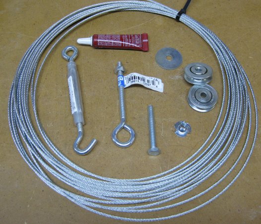
The installation requires 2 lengths of 3/16" cable, 4 cable crimp sleeves, 4 pulleys, 2 turnbuckes, 4 eye bolts,
2 1/4-20 "t" nuts, 2 1/4-20 fender washers, 2 1/4-20x2" cap screws, and some loctite.
The original forum discusses using sliding door wheels from the hardware store but these are made from plastic
and most don't have ball bearings. I was concerned that these may break or wear out quickly so I found some
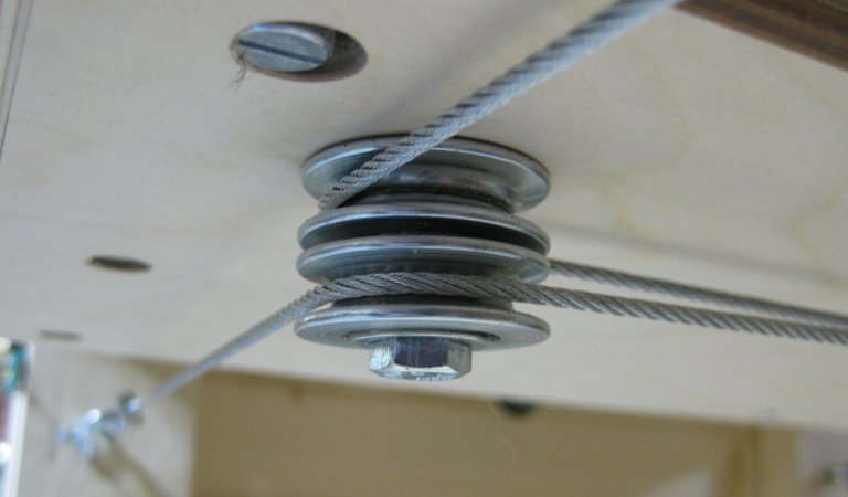
The pulleys are mounted on the 1/4-20 cap screw with a fender washer between the pulley and the wood (reduces stress
on the plywood by distributing the lateral force) then screwed into the 1/4-20 "t" nut mounted in the gantry bottom.
The pulleys are mounted vertically so that the cables can't contact each other where they cross in the center.
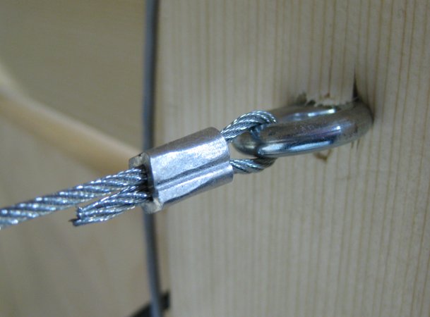
The eye bolts are mounted to the machine to be lined up with the pulleys and are adjusted with the turnbuckles.
If your gantry is narrower than mine, you may want to use the eye bolt as a pulley and put the turnbuckle below to adjust
the tension so that the gantry pulley doesn't hit it. The cables are terminated on the eye bolts by swaging them with
the crimp sleeves. If you don't want to spend the money on a swaging tool, then you can crimp these using a hammer
-- just tap them together then rotate 90 degrees and do it again. Don't overdo this or it won't be as strong.
After the turnbuckes are mounted, snug them up by hand (not too tight) and do some 90 degree corner test cuts and
accurately measure them. Alternately adjust the turnbuckles and perform test cuts until the machine is cutting perfectly
square. When you are done, the cables should be taught but not crazy tight. I get about 1/2" of deflection over a 2 foot
span using moderate finger pressure.
After installation, I tried to push on the gantry and was able to measure no deflection on the opposite side. The gantry
is now "Rock Solid"!
Here is a video of the system in action:
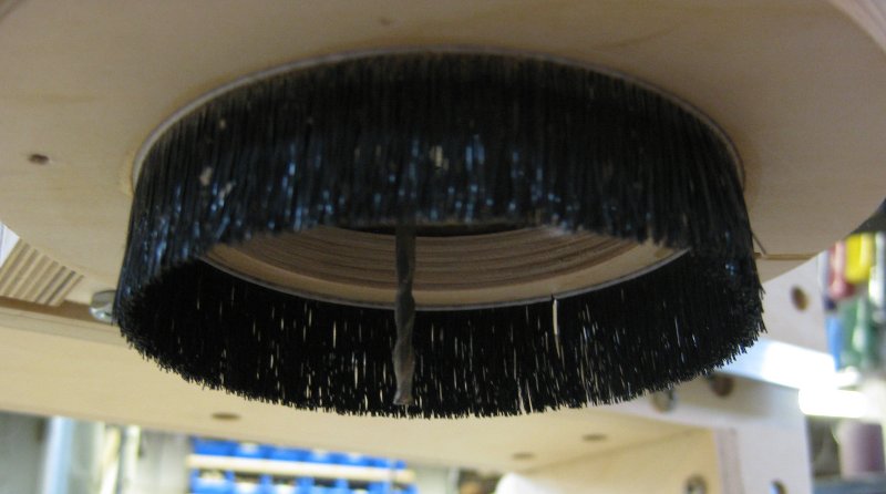
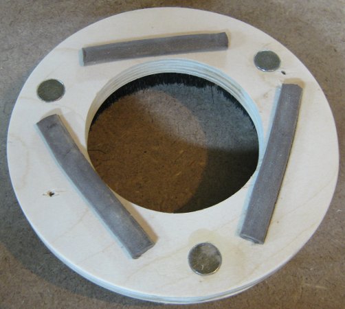
Spindle Dust Collector that Really Works
I have tried several dust collection methods over the past few years including everything from a vacuum hose wire-tied
to the router to several different kinds of brush/vacuum systems. The problems with many of the existing systems are that
you can't get the vacuum close enough to the bit at high enough velocity to pick up the dust and still leave room to be able
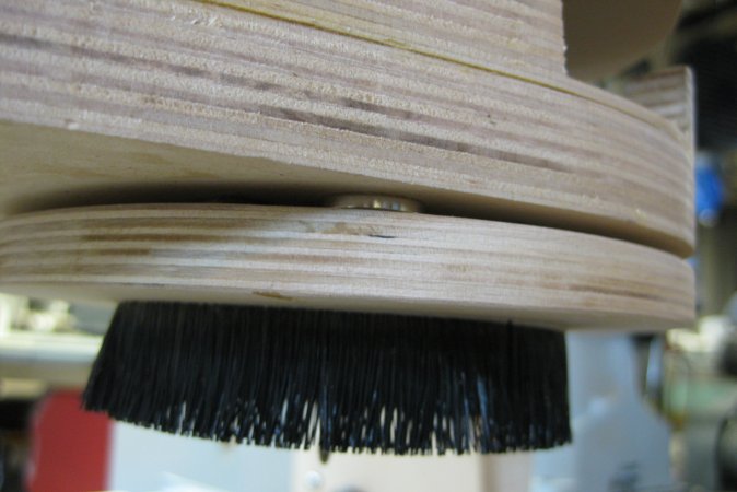
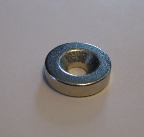
to change the bit. I have come up with a design that uses strong neodymium magnets to attach the lower dust brush. This allows
quick and easy removal of the brush assembly while allowing the vacuum to be directed where it is needed. The grey strips on the
right photo are pieces of weather stripping to keep the unit from sliding and reduce vacuum leakage. The brush is installed
(hot glued) into a 1/8" slot cut into the wood ring. The magnets are glued into 1/8" deep holes and are flush with the wood.
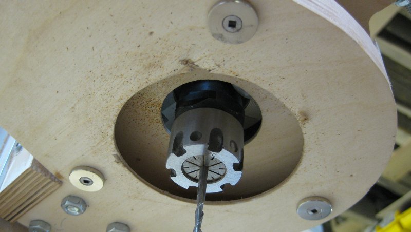
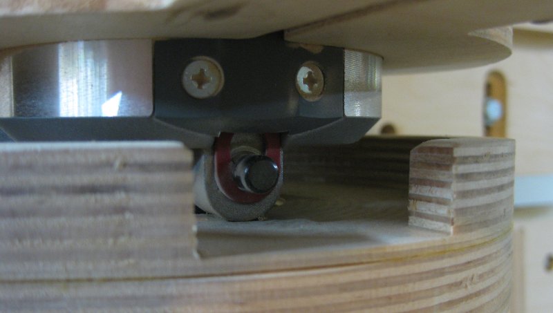
Notice that the fan output of this router (Porter Cable 890 Series) is redirected away from the vacuum while still leaving
access to the spindle lock to change bits.
The design is pretty straightforward. The magnets and magnet washers were purchased from
Rockler
(Woodcraft will also have these). The
brush was purchased on ebay -- just search on "dustbrush router"


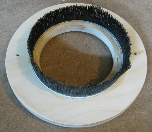
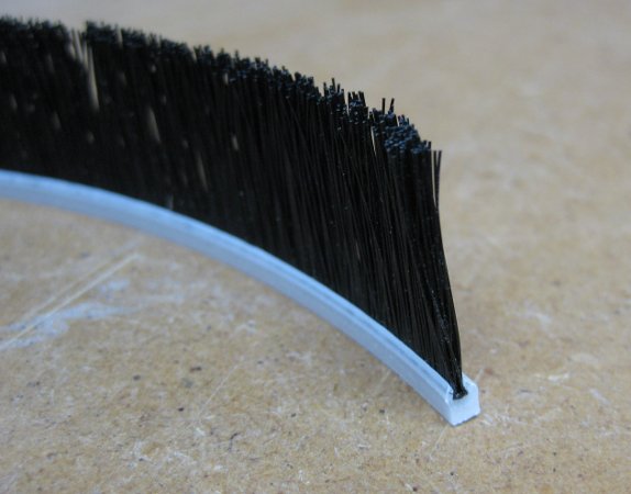