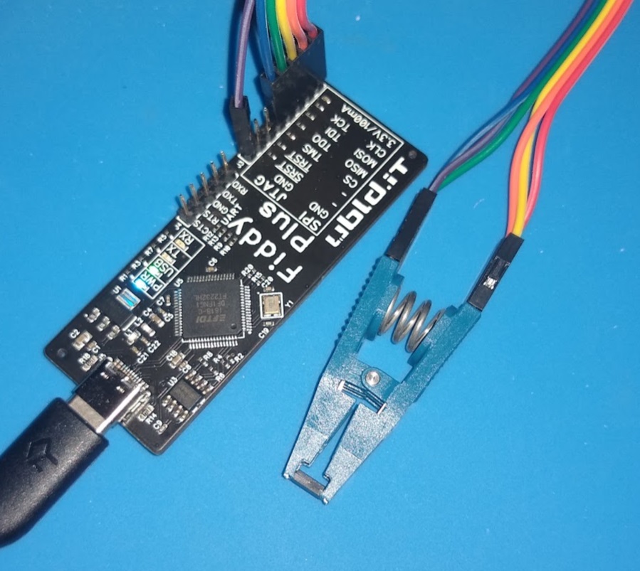
I designed this because of the lack of AUTHENTIC FT2232H boards out there. I've had trouble with signal integrity and drivers with some of the fake parts. This board can be used for readinging/writing SPI flash, JTAG, and several other purposes. I included the EEPROM one the board to allow programming using FT_Prog into other unusual modes.
Features Include
Genuine FTDI FT2232H
High-Speed USB JTAG, UART, or SPI Interface
Programming, debugging, testing, and reverse engineering using OpenOCD, UrJTAG, flashrom, iceprog, and others
On-board 93C56 EEPROM (for programming other FT2232H modes using FT_Prog)
I/O Protection Resistors and USB-C High-Speed Interface
I have received a number of emails on the performance testing of the TrueRNG. Every one of these have ultimately been attributed
to a small sample size or incorrect testing.
The TrueRNG products generate true random numbers - there is no guaranty that chi-squared or other statistical tests will
fall within any given range for a small sample size.
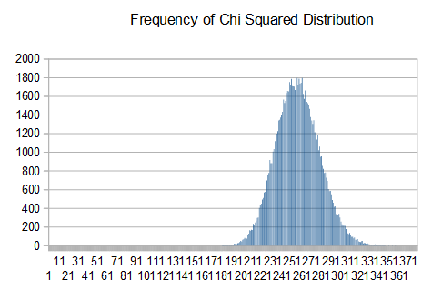
To show this, I captured a large number of 10k blocks from the TrueRNG and ran the 'ent' tool on each one and captured the results.
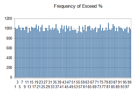
I then imported them into Openoffice Calc and did a frequency distribution on the chi-squared distribution and exceed percent values
Notice that the chi-squared values follow a normal distribution centered around 256 and that the exceed percent values have a uniform distribution. For a
large number of runs, this is the expected result.
From this, you can see that taking a small number of tests from a small sample size may give results that 'seem' bad. With a perfect generator, it is
expected to get percent values < 5 or > 95 in 10% of the results. If you don't see this distribution over a large number of runs, then there may be an issue.
It is expected that a true random number generator will fail statistical tests a certain percentage of the time.
For example, typical results from rngtest tool which runs FIPS 140-2 tests are:
Copyright (c) 2004 by Henrique de Moraes Holschuh
This is free software; see the source for copying
conditions.  There is NO warranty; not even for
MERCHANTABILITY or FITNESS FOR A PARTICULAR PURPOSE.

rngtest: starting FIPS tests...
rngtest: entropy source drained
rngtest: bits received from input: 114688000000
rngtest: FIPS 140-2 successes: 5729915
rngtest: FIPS 140-2 failures: 4484
rngtest: FIPS 140-2(2001-10-10) Monobit: 595
rngtest: FIPS 140-2(2001-10-10) Poker: 548
rngtest: FIPS 140-2(2001-10-10) Runs: 1653
rngtest: FIPS 140-2(2001-10-10) Long run: 1708
rngtest: FIPS 140-2(2001-10-10) Continuous run: 0
rngtest: input channel speed:
 (min=1713062.099; avg=9994464560.376; max=0.000)bits/s
rngtest:
 FIPS tests speed: (min=1.557; avg=82.152; max=85.531)Mibits/s
rngtest: Program run time: 1343537517 microseconds
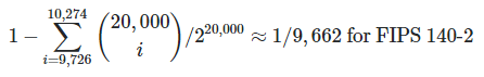
Notice that there are 5729915 successes and 595 Monobit failures (out of 5734399 runs). For FIPS 140-2, the monobit test is EXPECTED to fail
about 1 out of every 9662 runs with a perfect random source.
For 5,734,339 runs, we would expect about 593.5 failures which is very close to the actual number of failures of 595. Similarly, a certain number of failures
is expected for each of the tests (except for the continuous run obviously).
Notes on other failures
For Dieharder, using the correct options and having sufficient input data is very important. You need 14+ gigabytes of input data to run dieharder with a small number of rewinds.
Having a small data file input feeds the same data multiple times into the test and often gives false 'FAILED' results. I run most dieharder tests with:
dieharder -g 201 -k 2 -Y 1 -f FILENAME
-g 201 = use external file as input
-k 2 = use maximum accuracy to machine precision (slower)
-Y 1 = resolve ambiguity mode = reruns 'WEAK' results until PASSED or FAILED result is obtained
-f FILENAME = the name of the file to use for the source
As with other statistical tests for random number generators, it is expected that each dieharder test gets a 'FAILED' result a certain percentage of the time.
A single of small number of failures on a particular test is not a cause to label the generator as bad. For a 'FAILED' result, a particular test can be re-ran on
the same input file with a larger block size to show that the failure is an anomaly.
I use the following to re-run a single particular dieharder test and increase the p_value multiplier (-m) and/or use split to chop up the input file into chunks then
test each one separately (re-running the same test on the same input will get the same result and not tell you anything about the rest of the file)
-k 2 = use maximum accuracy to machine precision (slower)
-Y 1 = resolve ambiguity mode = reruns 'WEAK' results until PASSED or FAILED result is obtained
-m 2 = use twice the number of p_samples as input
-f FILENAME = the name of the file to use for the source
Dieharder Test Flags

-d 0                  Diehard Birthdays Test Good
-d 1                     Diehard OPERM5 Test Good
-d 2          Diehard 32x32 Binary Rank Test Good
-d 3            Diehard 6x8 Binary Rank Test Good
-d 4                  Diehard Bitstream Test Good
-d 5                            Diehard OPSO Suspect
-d 6                       Diehard OQSO Test Suspect
-d 7                        Diehard DNA Test Suspect
-d 8      Diehard Count the 1s (stream) Test Good
-d 9        Diehard Count the 1s Test (byte) Good
-d 10               Diehard Parking Lot Test Good
-d 11          Diehard Minimum Distance Test Good
-d 12                 Diehard 3d Sphere Test Good
-d 13                   Diehard Squeeze Test Good
-d 14                      Diehard Sums Test Do Not Use
-d 15                      Diehard Runs Test Good
-d 16                     Diehard Craps Test Good
-d 17           Marsaglia and Tsang GCD Test Good
-d 100                      STS Monobit Test Good
-d 101                         STS Runs Test Good
-d 102         STS Serial Test (Generalized) Good
-d 200             RGB Bit Distribution Test Good
-d 201 RGB Generalized Minimum Distance Test Good
-d 202                 RGB Permutations Test Good
-d 203                   RGB Lagged Sum Test Good
-d 204      RGB Kolmogorov-Smirnov Test Test Good
-d 205                     Byte Distribution Good
-d 206                               DAB DCT Good
-d 207                    DAB Fill Tree Test Good
-d 208                  DAB Fill Tree 2 Test Good
-d 209                    DAB Monobit 2 Test Good
If there is consistent failure on a particular test using multiple input runs and the test is not suspect, then there may be something wrong with the
random number generator or testing methodology.
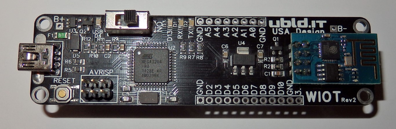
Wireless Internet Of Things (WIOT) Final Version
I designed this board to be an easy-to-use way to get connect to WiFi from an Arduino-compatible board. This will
allow anyone to write Arduino compatible sketches that can easily use 802.11b WiFi using the ESP-8266 (ESP-01)
WiFi module.
Although I could have probably done this as a successful Kickstarter campaign, we did the development on our
own and ran a first batch of 50 units. If these are popular, we will run a larger batch.
We have updated the firmware on the ESP-8266 to operate at 9600bps by default
(Thanks to electrodragon) since an 8MHz ATMEGA can't
generate 115,200bps. This may be reprogrammed by the user using AT commands (be careful not to program it
to something you can't talk to)
The included 18650 battery holder may be used to power the device from a 18650 battery. We recommend
a high-quality 18650 with built-in protection circuitry such as the
Nitecore NL189
One of the problems that we noticed when using other battery powered boards is that even with a low-dropout
regulator, the addition of a diode-based power switching circuit limited the power than can be used from the
battery. A switching circuit is necessary to keep external power from feeding back into the battery directly which
will damage both the battery and charging circuitry. Using a .1V dropout regulator in series with a .25V drop Schottky
diode means that for a 3.3V regulator you need 3.65V on the input. Most lithium-ion batteries have a significant amount of
capacity left at that voltage that can't be used without the 3.3V sagging. Using our circuit, we can run down to 3.4V
without affecting the regulated 3.3V. The 18650 lithium-ion batteries are about 95% discharged at 3.4v.
Here is a demo of the low-voltage drop auto power switching
Features include:
Arduino Compatible
ATMEGA32U4 at 8MHz
On-board Lithium Ion Battery management
Automatic switching from external 5V power to battery
Any 5V (500mA) source may be used to power and charge the unit
ESP-8266 WiFi Module (ESP-01) with updated firmware (9600bps default)
Uses a through-hole Mini-USB connector (I got tired of pulling the Micro-USB off of the WIOT prototype and
other red Arduino-compatible boards that I won't call out by name)
With proper power management and intermittent WiFi usage, the battery can last for days to months (depending on
sleep time, WiFi usage, WiFi Transmit usage, and other peripherals) without recharging. On-board switching allows for
complete power-down of the ESP-8266. Since the board auto switches between external and battery power,
a USB solar charger may be connected to power the unit indefinitely.
The board runs a modified version of the Arduino Caterina bootloader. The bootloader has been modified for this board
and to extend the length of time that the board stays in bootloader mode after a reset "double-tap". During development, it
was annoying to have to rush to quickly load blink after a failure before the device reset and tried to run code.
I tried to get into the Arduino At Heart program but couldn't get any technical cooperation from them. After several emails,
they just quit responding to me so I'm releasing the firmware as an "Addon" like several other popular Arduino-compatible
boards do. Basically, just unzip the zip file into your Arduino root directory and it should show up as a board in the Arduino IDE.
I have tested with the 1.5.8 and 1.6.1 versions of the Arduino IDE.
The board comes with a Signed USB .inf file (no crazy stuff to get Windows 7/8/etc working) that uses the standard
Windows USB serial driver. Just right-click on the ubld_wiot.inf file and choose install. Your WIOT board should then
show up as a windows COM port and be functional in the Arduino IDE.
As for Arduino sketches, it works as any other Arduino. Paul King helped me get the WiFi demo sketch working
reliably. The firmware in the ESP-8266 can't handle a lot of connections at one time so we have set it up to reset
the device in the event of buffer overflow/data loss/other strangeness to make sure that it will still communicate.
Here is a video of the WIOT Wifi Demo. It is a simple web server that uses buttons to control LEDs on the WIOT board.